Save Time and Effort with On-Sensor Polarization
Why use on-sensor polarization?
Many vision systems struggle to overcome the effects of dynamic or excessive light, reflections, haze, and glare from shiny surfaces like glass, plastic, and metal. Blackfly S machine vision cameras featuring Sony’s on-sensor polarization and anti-glare features built into Spinnaker SDK provide an easy to implement, lightweight and reliable solution to address such challenging situations. With precise and dynamic control over exposure, gain, white balance, and color correction, Blackfly S cameras featuring on-sensor polarization capture light from four angles in a single frame - significantly reducing system complexity and application design.
Systems that rely on multiple cameras and filters behind a beam-splitting prism, or a single camera with a rotating filter or filter wheel, are large, complicated, and slow. By simultaneously sensing the angle and intensity of all polarized light across the sensor, Blackfly S cameras with polarized sensors deliver increased speed, reduced size, complexity and power consumption compared to existing solutions.
Supported camera models:
Blackfly S GigE cameras featuring on-sensor polarization
BFS-PGE-123S6P-C: 12.3 MP, 10 FPS, Sony IMX253MZR, Polarized
BFS-PGE-51S5P-C: 5.0 MP, 24 FPS, Sony IMX250MZR, Polar-Mono
BFS-PGE-51S5PC-C: 5.0 MP, 24 FPS, Sony IMX250MYR, Polar-RGB
Blackfly S USB3 cameras featuring on-sensor polarization
BFS-U3-51S5PC-C: 5.0 MP, 75 FPS, Sony IMX250MYR, Polar-RGB
BFS-U3-51S5P-C: 5.0 MP, 75 FPS, Sony IMX250MZR, Polar-Mono
When on-camera polarization is useful:
Unmanned Aerial Systems (UAS)
Applications like UAS or drones typically operate outdoors in uncontrolled lighting conditions. The Blackfly S provides four sets of polarized images, with polarization angles at 90°, 45°, 135° and 0°, to compensate for changing lighting conditions and the relative movement and orientation of the UAS. By providing application engineers 4 sets of polarized images per frame, the Blackfly S reduces system complexity, payload weight and failure points while improving image quality and decision time in challenging lighting conditions.
Intelligent Traffic Systems (ITS)
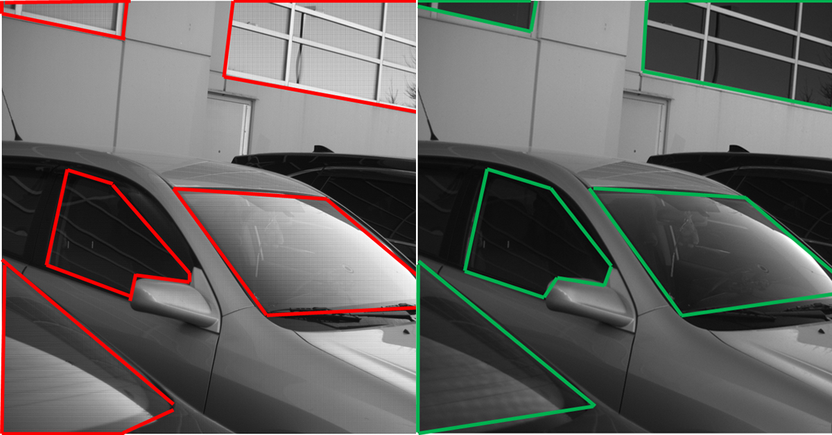
Using a polarized filter setup is challenging for ITS applications like seatbelt or mobile device violations imaging through reflective windshields, as outdoor lighting conditions change throughout the day. Some systems overcome this with multi-camera / filter setups, significantly compromising on system reliability while increasing hardware and maintenance costs. On-camera polarization can simultaneously capture four sets of images per frame; ensuring at least one of these images is effective at eliminating unwanted reflection. Application developers are afforded the flexibility of choosing one or multiple polarized images during post processing – saving time and money on development, integration and maintenance.
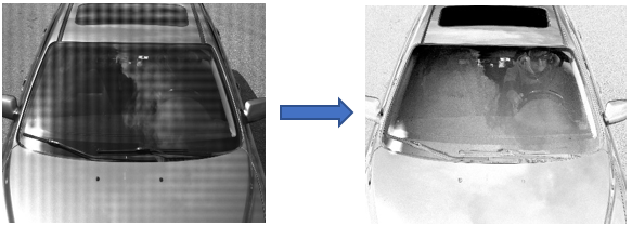
Reflections on a windshield under outdoor lighting conditions; with and without polarization.
Detection and identification
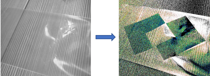
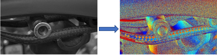
Polarimetry is ideal for detecting objects that would otherwise be difficult to identify using traditional visible or thermal imagery. Camouflaged vehicles or microscopic cell structures continue to reflect polarized light oriented parallel to the surface; these reflections stand out clearly in AoLP mode (Angle of Linear Polarization), as illustrated below.
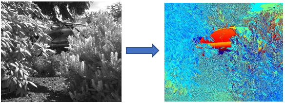
A well camouflaged vehicle before and after utilizing on-sensor polarization
Optimizing deep learning (DL) for AUVs and USV’s
Decluttering images by removing unwanted glare and reflections can simplify the training of deep learning systems. This is particularly useful in high-glare environments encountered by autonomous vehicles and marine submersibles (Unmanned Surface Vehicles - USVs).
Other applications
The high resolution and low read noise of Blackfly S cameras enable a wide field of view to be analyzed with standard microscopy equipment (for example, the polarizing properties and optical activity of biological compounds can differentiate healthy and diseased tissues). Several other applications like semiconductor and electronics manufacturing, flat panel display (FPD) manufacturing and inspection, food packaging, cosmetics, pharmaceutical packaging, logistics, microscopy, and inspection deal with reflective surface areas, where on-camera polarization can be particularly useful.
What makes Blackfly S cameras featuring Sony’s polarized sensors different?
Sony’s On-Sensor Polarization
Sony’s IMX253MZR and IMX250MZR sensors are based on their popular twelve and five-megapixel IMX253 and IMX250 Pregius global shutter CMOS sensors. Each individual pixel has its own polarizing filter - these filters are oriented to 0°, 45°, 90° and 135° and arranged in repeating two-pixel blocks. These sensors have features that minimize the impact of reduced quantum efficiency (QE) resulting from adding polarizing filters to pixels. For instance, the polarizing filters of the IMX250MZR have an extinction ratio of 300:1 at 525 nm, which is high enough to deliver accurate polarimetric data without blocking cross-polarized light. This ensures that even when filter alignment passes a minimal amount of light, enough light will reach the light-sensitive photodiode to capture useful images. This enables capture of low-noise images even in challenging conditions requiring gain to compensate for reduced QE.
Spinnaker SDK with anti-glare and reflection removal features
Spinnaker SDK supports API calls to create a glare reduced image from the source images by choosing the darkest pixel from each polarization quadrant. Using polarimetric measurements, it can dynamically reduce reflections from non-metallic surfaces, thereby reducing system complexity, and saving application development time. See example below:
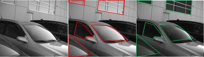
L - Raw polarized image | M - Polarized image with subject of interest highlighted in red | R - Processed image with anti-glare reduction enabled
Higher frame rates (with Lossless Compression)
Blackfly S GigE cameras with Sony’s polarized CMOS image sensors enable higher frame rates at high resolution (e.g., up to 14 FPS at 12 MP) without losing any image data by utilizing Lossless Compression built into the camera’s firmware. This increased processing speed and high resolution can be particularly useful in highly demanding industrial and research-oriented applications.
Interpretation of polarization data
Interpretation and characterization of polarization parameters of light require measurements from all four angles of polarization. To achieve this for each pixel on the sensor, an interpolation process is required, where data from adjacent pixels are combined. This is analogous to how data from adjacent red, green, and blue pixels is combined on color sensors to produce RGB values for each pixel. This process is natively supported by Spinnaker SDK.
Combining polarization and color
The IMX250MYR sensor adds a color filter array to the sensor below the polarizing filters. This sensor uses a unique Quad-Bayer pattern which prioritizes spatial resolution of the polarization domain over spatial resolution of color information.
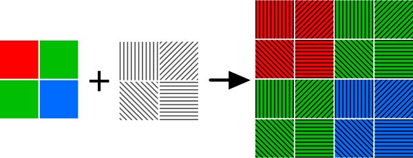
RGB pixels rearranged into 2x2 “super-pixels”. Each super-pixel has one polarizing filter per orientation and contains all the information necessary to compute the Stokes parameters at that location.
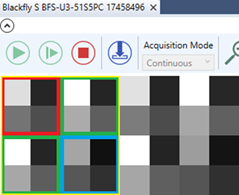
Screenshot of Spinnaker SDK GUI highlighting 2x2 ‘super-pixels’
Global shutter function
Rolling shutter CMOS image sensors are unable to accurately identify fast-moving objects, due to focal plane distortion. Blackfly S cameras with Sony’s new on-sensor polarized sensors address this issue by providing an analog memory inside each pixel, delivering a global shutter function to enable high quality images without focal plane distortion.
Additional reading:
Light is a transverse electromagnetic wave. As it propagates, it oscillates perpendicular to the direction of propagation. Most light sources emit unpolarized light, with all the waves oscillating at random angles. When light is aligned so that most waves oscillate at a common angle, it is said to be polarized. Circular polarization is also possible, though it is beyond the scope of this guide.
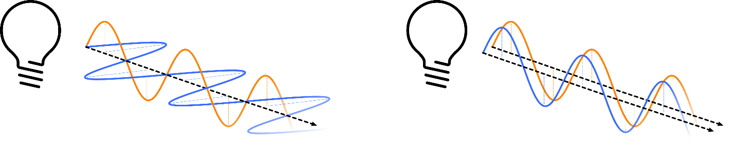
Unpolarized light oscillating at random angles vs. Polarized light aligned on an angle
Polarizing filters
Polarizing filters form the foundation of most polarized light technologies. By aligning a series of narrow slits, polarizing filters pass light that is oscillating perpendicular to the slits while blocking light oscillating parallel to them.
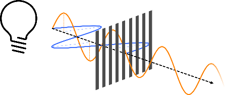
The polarizing filter passes the yellow beam that is parallel to the polarizer axis (or perpendicular to the angle of the slits), and blocks the blue beam aligned perpendicular to the axis of polarization (or parallel to the slits angle).
Industrial applications frequently rely on a pair of polarizing filters; one that creates a polarized light source and another that passes only polarized light aligned to a specific orientation. These systems typically require precisely aligned filters and highly controlled lighting. They are only sensitive to one angle of polarized light.
As a polarizing filter is rotated, the intensity of the light it passes will increase as it comes into alignment and decrease as it is moves beyond the angle of alignment.
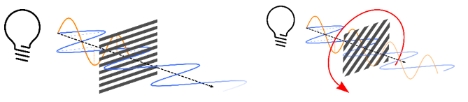
As a polarizing filter aligned to the angle of the blue wave is rotated, it begins to block the blue wave and pass the orange one.
When plotted, the change in intensity relative to polarizer orientation is like a sine function. The ratio between the highest and lowest intensities is called the extinction ratio.
Due to the transverse nature of light, angles of polarization cannot exceed 180°. As the slits in a polarizing filter are all parallel, rotating a filter by 180° will return it to its original orientation. This explains why the intensity peaks and falls off twice as the filter is rotated by 360°.
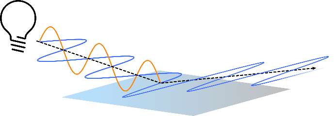
How does light become polarized?
Light can become polarized when emitting directly from a coherent source, passing through a polarizing filter, or reflecting off a non-metallic surface. The angle of polarized light reflected off water or a polished surface is parallel to surface.
The angle of polarized light can change as it passes through certain optically active materials, such as biological molecules and pharmaceuticals.
Stokes parameters
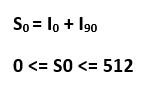
The four Stokes parameters are a convenient way of describing the polarization state of a light beam. Stokes parameters are the basis of many polarimetry calculations and algorithms. Users wishing to adapt existing techniques or create their own should be familiar with how to determine the Stokes parameters on the IMX250MZR.
S0 is the intensity of light beam. On the IMX250MZR, this is calculated by adding the intensities of the vertically and horizontally polarized pixels.
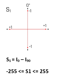
S1 is the difference between the horizontal and vertical components. Positive values are horizontally linearly polarized while negative ones are vertically linearly polarized.
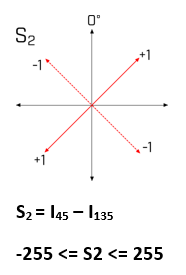
S2 is the 45° component. Positive values are 45° linearly polarized. Negative values are -45° or (135° if you will) linearly polarized.
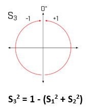
S3 is the circular polarization component. Though this parameter is not measured by the IMX250MZR, it can often be accurately estimated. In outdoor and passively illuminated environments, S3 is assumed to be 0 since sunlight is unpolarized and reflection or scattering of sunlight only imparts linear polarization.
In environments with controlled active illumination, it is possible to eliminate any sources of unpolarized light, making it possible to characterize the circular component.
The S1, S2, and S3 Stokes parameters are frequently represented as a set of spherical coordinates mapped to a Poincaré sphere. This notation is a convenient way of understanding the relative contribution of each of the polarized components of a light beam to its overall polarization state.
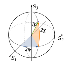
Poincaré sphere. Outdoors, the S3 component can reliably be assumed to be 0. The intensity, Ip is equal to 1.
Stokes parameters can be used to compute polarimetric parameters and greatly enhance visible spectrum imagery.
Degree of Linear Polarization
The Degree of Linear Polarization (DoLP) is the most basic way to interpret polarization data. DoLP is the proportion of light that is polarized at a given pixel. A perfectly polarized light source would have a DoLP of 100%, while unpolarized light would have a DoLP of 0%.
Difference between DoLP of 100% vs. DoLP of 0%
Angle of Linear Polarization (AoLP)
The Angle of Linear Polarization (AoLP) is the average polarization angle of the light at a given pixel. If the DoLP is low, only a small amount of light will be polarized. In this case, the resulting AoLP values will show clear spatial and temporal noise. This is analogous to a low intensity signal being amplified with high gain. As the DoLP increases, AoLP values will become less noisy.
See More Machine Vision
Related Articles
-
 Embedded Vision
Streaming 4x Cameras with Small Carrier Board: Fast Prototype
Read the Story -
 Embedded Vision
How to Build a Custom Embedded Stereo System for Depth Perception
Learn more -
 Embedded Vision
Guide for Integrating Board Level Cameras
Read the Story