Using Acoustic Imaging for Partial Discharge Monitoring
Partial discharge (PD) is a maintenance challenge found on high-voltage equipment around the world—especially older, aging infrastructure. Predictive maintenance workers are now starting to use acoustic imaging to target PD by finding its distinctive sound signature even before equipment overheats. When used in tandem with FLIR infrared cameras, acoustic imaging cameras like the FLIR Si124 are indispensable to effectively find PDs before they lead to equipment failures, costly damage, and unexpected downtime.
Electric current is always looking to escape when no one is looking, leaping from its conductor, and trying in vain to bridge across to a nearby electrode. On the lookout for an escape route, it starts with a crack in a tired insulator. Or, it begins on the surface of an overhead line’s insulator, dirty with years of pollution. Maybe it pokes a tiny pinhole in the paper windings of high-voltage cables. Or it hides near a gas bubble that formed in aging liquid dielectric. It is relentless, trying again and again with every high and low peak of the voltage sinewave.
Utilities can reduce inspection time by up to 90 percent without extensive training using the FLIR Si124.
This type of partial discharge or PD remains hidden from view as the current attempts to cross to a neighboring conductor day after day. At some point, having deteriorated from the constant high voltage stress, nearby insulating material will fail and give way.
Finally, the current breaches the divide to another conductor and when that happens, the conductor will fail completely. This wreaks costly and destructive havoc on electrical equipment, switch gear, machinery, or facilities down the line. PD can damage plant equipment or fry sensitive electronics. Even worse, PD can shut down power to a community for hours or idle plant shifts, costing valuable productivity.
IEC 60270 more formally describes a PD as a ‘‘localized electrical discharge that only partially bridges the insulation between conductors and which can or cannot occur adjacent to a conductor. In general, a PD is the consequence of local electrical stress concentrations in the insulation or on the surface of the insulation and generally appear as pulses having a duration of much less than 1 μs.’’
PD DIAGNOSTICS—ESSENTIAL FOR PREDICTIVE MAINTENANCE
Detection of PD is a must-have part of an effective condition-based monitoring (CBM) or predictive maintenance (PdM) program. The earlier they are detected, the less damage a PD can cause to insulators and the lower the risk of equipment failure and subsequent down time.
The financial incentive to track down a PD is simple: It’s much less expensive and disruptive to locate one, plan for scheduled downtime, and then repair and replace insulators and electrical connections at the site of the PD.
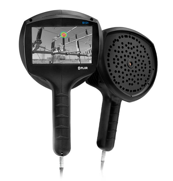
FLIR Si124 Acoustic Imaging Camera
TOOLS FOR SUCCESS
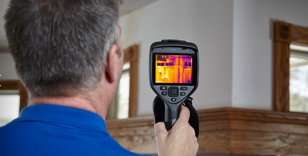
To locate a PD accurately, numerous diagnostic technologies are available for electrical contractors, inspectors, and maintenance professionals. Insulation testing meters provide numerical readings of how effective or resistive an insulator is. Thermal imaging cameras from FLIR locate and identify the resistive heat generated on electrical equipment, pinpointing it in a visual image with pixel-by-pixel temperature readings. Thermal imaging can be used in conjunction with acoustic imaging to determine the severity of PD. A rise in temperature along with an acoustic signature could indicate insulative equipment integrity is compromised.
LOCATE PD INSTANTLY
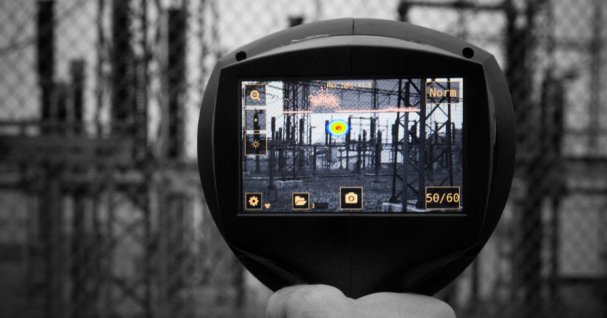
As part of a complete diagnostic ecosystem, FLIR also complements infrared thermal imaging diagnostics with acoustic imaging capabilities. Acoustic imaging cameras, such as the FLIR Si124, offer advanced sound-based solutions for locating and analyzing industrial faults, deterioration, and defects such as a PD. Anomalies in sound generated by PD have been found to occur before components start to heat up and become visible to thermal imaging cameras. This provides an additional layer of advance notice in detecting potential future failures.
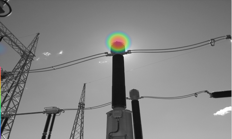
And while it’s not unusual to hear humming or buzzing near power lines, PD is often inaudible to human hearing, making them particularly difficult to locate, especially in noisy work sites with excess background noise. Using a handheld acoustic imaging camera, much like a thermal imaging camera, a user can scan an area and actually see the location of ultrasonic sounds generated by PD on a digital image of components being inspected—whether inaudible or cloaked by background sound.
PORTABLE, ONE-HANDED OPERATION
While numerous tools are available to electrical workers to perform acoustic imaging, there are notable considerations to keep in mind, from portability to precision.
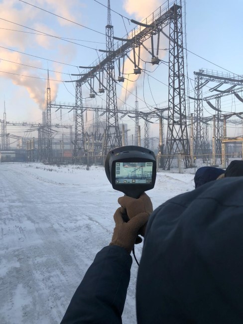
First, while most acoustic imaging tools are portable, select one that is easy to carry from site to site. Consider an acoustic imaging camera that is handheld, ready to use, and easy enough to hold with one hand, making it useful for transport, ergonomics, and improved aiming.
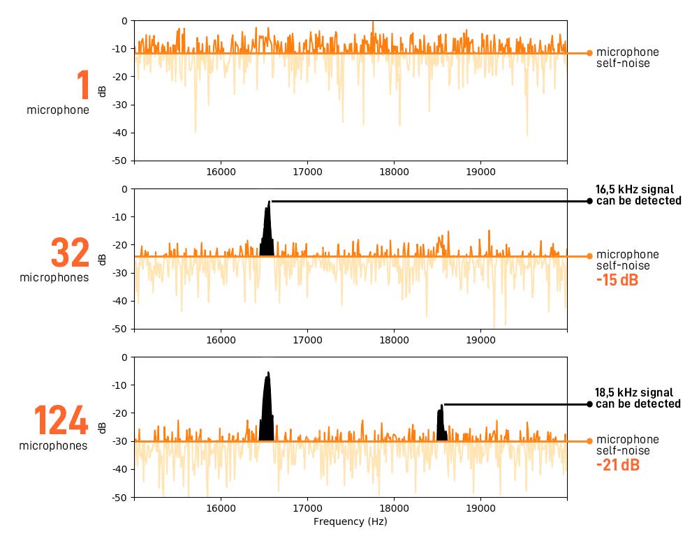
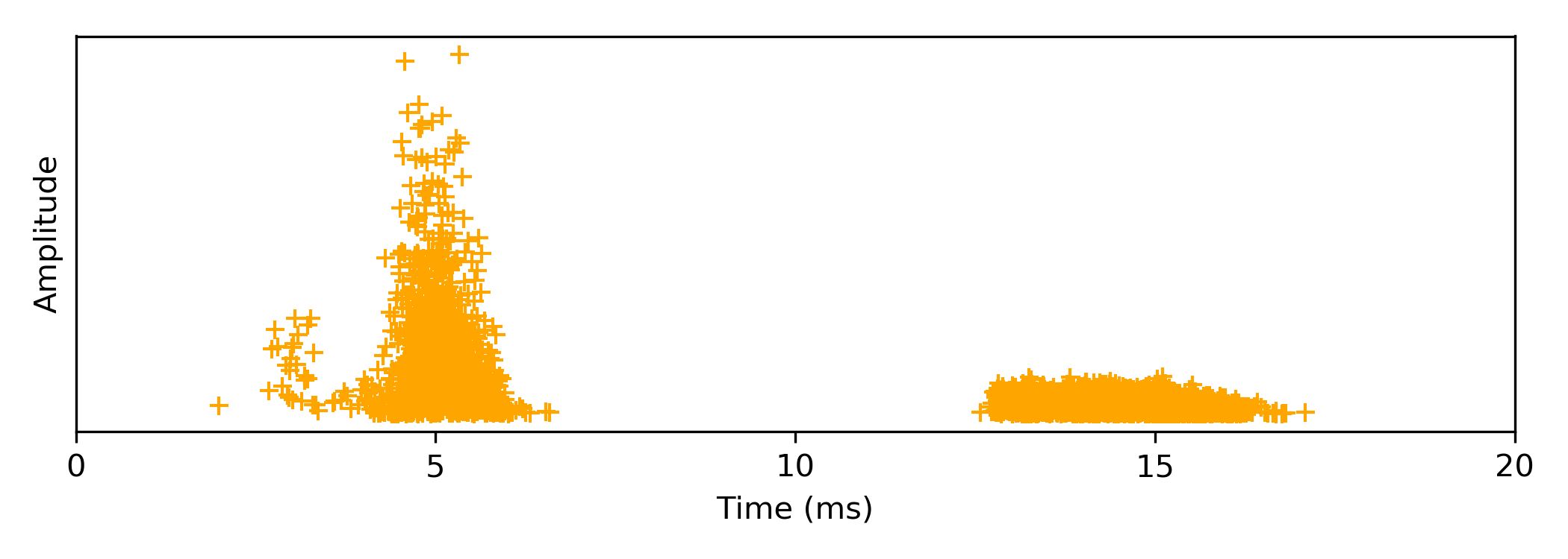
This illustration shows two signals from two sounds that can be missed if the acoustic camera’s sensitivity is not good enough. The 16.5 kHz sound signal can be detected with a system of 32 microphones and the 18.5 kHz sound signal with a system of 124 microphones.
MORE MICROPHONES, BETTER RESULTS
The range of acoustic imaging tools available also reveals a wide mix in the number of microphones employed to develop acoustic images. As a general rule in technology, more is better, so it goes without saying that employing more microphones is essential to creating richly detailed acoustic images. As with technology again, bigger isn’t always better when it comes to microphones. Look specifically for MEMS (microelectro–mechanical systems) type microphones. These can offer users a good balance of performance, stability in different environments, low-power consumption for smaller batteries, and longer runtime. Plus, the microphones’ small size means it’s easier to arrange them in a compact manner on a handheld tool.
Sensitivity: Examining the FLIR Si124 acoustic imaging camera, there is a carefully arranged array of 124 MEMS microphones that, working together, offer the highest level of sensitivity. The higher number of microphones also reduces the potential for “spatial aliasing”, which is the improper positioning of the sound source on the image.
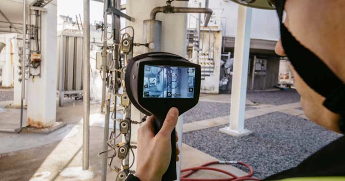
An acoustic imager such as the FLIR Si124 can help utilities analyze electrical partial discharge patterns, prioritize repairs with the automated leak cost estimates and discharge type classification, and quickly and safely conduct non-contact inspection.
Detection Range & Access: Another advantage secured by a large number of microphones is an expanded detection range. Keep in mind that sound traveling through air is attenuated by 6 decibels with every doubling of the distance traveled. A mid-sized partial discharge might measure 40 dB(Z). The sound heard from 15 meters (approx. 50 feet) away from the source is 6 dB stronger than at 30 meters (approx. 100 feet), and so forth. To compensate for this, acoustic imaging camera makers increase the count of microphones to increase the detection range. For FLIR, the result is a maximum detection range that approximately doubles by using four times the number of microphones.
Many electrical components are difficult to access due to being fenced off for safety or situated high off the ground. Access restrictions might also be time-based—limited to when a customer contact is on-site to permit entry. Given these barriers to access, it is critical to use tools that can accurately find PD, even at a distance. For example, the FLIR Si124 can be used to inspect wires overhead from the ground as well as substation components that are secured behind fencing—up to 130 meters (426 feet) away.
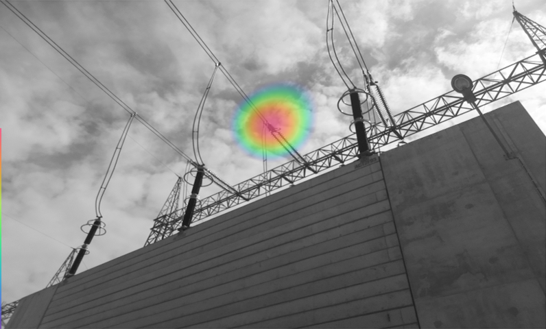
The FLIR Si124 can be used to inspect wires overhead from the ground as well as substation components that are secured behind fencing—up to 130 meters (426 feet) away.
Processing Power: The FLIR Si124 produces 124 streams of audio data that are processed and converted to a visual display. The camera has automatic sound frequency selection which simplifies the usage without sacrificing performance. Advances in data and graphics processing power have made it possible to integrate such vast amounts of acoustic data instantly into an easy-to-understand image on the screen.
Users who compromise with cameras that have fewer microphones and/or older processors can end up with lower quality images, lower resolution, and potentially a slower refresh rate. In terms of productivity, a state-of-the-art camera like the FLIR Si124 can find problems up to 10 times faster compared to other tools available.
MICROPHONE FREQUENCIES CAN IMPACT INSPECTIONS
Inspection tools used by electrical contractors can, by themselves, promote misconceptions about how best to identify PD. For example, PD consistently emits ultrasonic sound at a common frequency (40 kHz). Many acoustic imaging devices almost exclusively use or recommend just this frequency. While that might be useful in some cases, in many others, it can significantly impair detection sensitivity. Using a wider range of frequencies, from 10 kHz to 30 kHz, can yield better results when working from a distance, such as at an outdoor substation.
Smart Noise Cancellation: PD generates broadband sound, extending from audible to inaudible or ultrasonic frequencies. Additionally, inspections rarely take place in silent sites. Instead, devices must contend with background noise from industrial facilities or outdoor sites, near highway or aviation noise, for example. Smarter acoustic imaging cameras can make sense of interference and background noise, filtering it out to isolate the PD culprit.
PUTTING AI & THE CLOUD TO WORK IN PD DIAGNOSTICS
Categorizing PD is often challenging. FLIR aids electrical contractors by applying AI algorithms to analyze partial discharge. A user can upload acoustic images to the FLIR Acoustic Camera Viewer cloud service and the image is automatically compared to thousands of PD images. The cloud service classifies the PD found among three main categories: surface, floating, and discharge in air.
Reliance on an advanced AI service can help reduce errors, accelerate report preparation, and serve as a key differentiator for inspection clients. The added ease-of-use also helps on-board more workers to perform acoustic imaging inspections as part of condition-based monitoring or predictive maintenance.

Equipped with AI-powered presets for locating and analyzing partial discharge, the FLIR Si124’s frequency range and microphone grid are optimized to automatically remove interfering noise.
DECIDING ON THE RIGHT ACOUSTIC IMAGING TOOL
Acoustic imaging has rapidly grown into must-have technology to keep power infrastructure up and running. More CBM managers are adding cameras like the FLIR Si124 to their toolbox. The return on investment comes rapidly as they find problems quickly and easily while repair costs and unplanned downtime are reduced.
PD CLASSIFYING CAPABILITIES TO CONSIDER
Analyzing acoustic images can take some training and learning, especially when it comes to understanding different types of PD that have been located. Knowing what issues are apparent and the severity can help in formulating better reports, better repair recommendations and smarter next actions.
There are several types of PD, based on where the discharge is occurring and its pulse pattern. Surface discharges appear at the boundary of different insulation materials. Surface discharges can be found in a number of locations including bushings, cable terminations, or generator windings that are overheating.
Example of the PD pattern of a surface discharge.
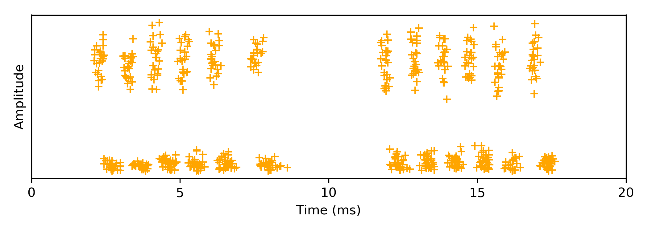
Example of the PD pattern of a floating discharge.
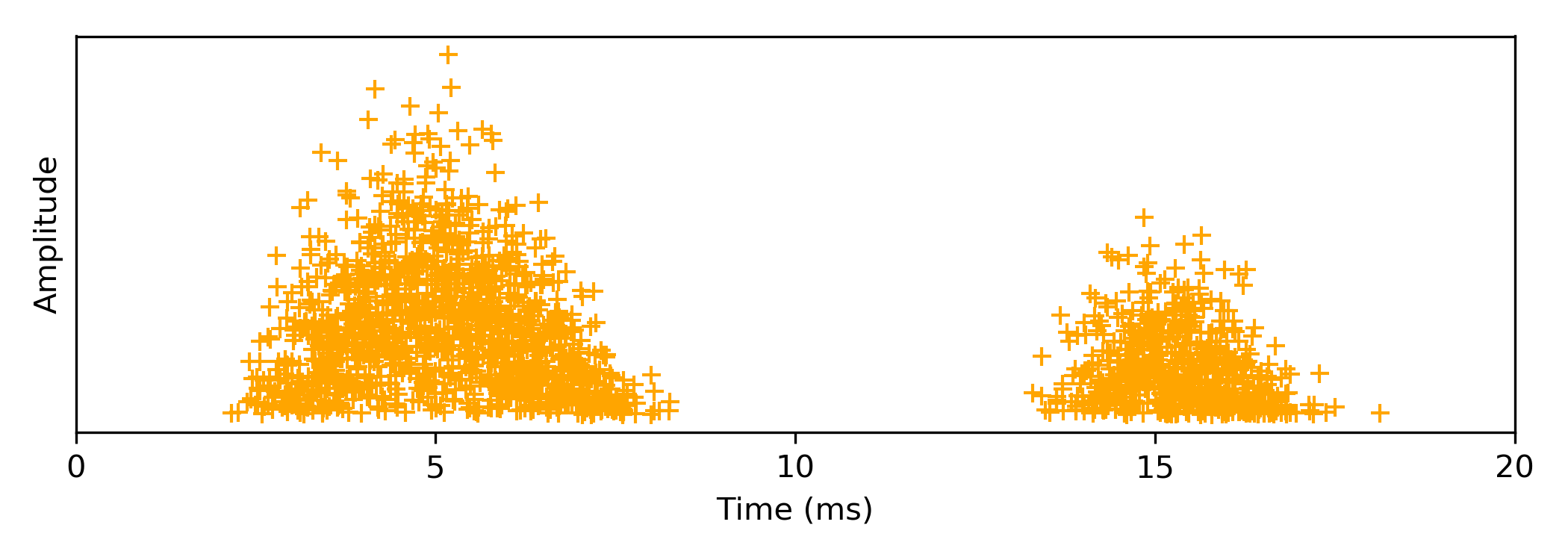
Example of the PD pattern of negative and positive corona discharge. Positive corona is seen on the left and negative corona on the right side.
Floating discharges can occur when there is a floating conductor inside high voltage equipment, separated by a spacer for example. Floating discharges are considered to be the most frequently occurring form of PD.
Finally, partial discharge into air occurs when air around a conductor, such as a power transmission line, serving as insulating material, may lose some of its insulating properties in high humidity and/or pollution. This permits discharges into the air which further degrades the immediate air quality and the conductor.
Knowing the type and severity of the discharge enables the facility targeting of appropriate remediation measures, schedule maintenance to minimize failures and downtime.
Equipment areas to target for partial discharge acoustic imaging
- Conductors and busbars
- Electric generators
- Electric power transmission and distribution (T&D)
- Electrical substations
- Stators, motors and coils
- Switchgear
- Transformers
Programs that use partial discharge acoustic imaging
- Condition-based maintenance programs (CBM)
- Condition monitoring programs (CM)
- Predictive maintenance (PdM)
For more information about thermal imaging cameras or about this application please visit: www.FLIR.com/si124
Related Articles
-
 Recorded Webinar
Webinar: Intelligent, Sound-Based Solution for Industrial Condition Monitoring with FLIR Si124
Watch now -
 Case Study
Manufacturers are driving down rising energy bills with acoustic imaging
Read the Story -
 Others
Improve Condition Monitoring with Thermal and Acoustic Cameras
Read the Story