Web Interface Exercise
Objective: This exercise is intended for people not used to the FLIR A400/A700 series cameras and for those who needs a quick understanding of the features that are new, such as the polyline. The web interface is much more complex than what this exercise covers, but it is a good starting point for getting to know the camera.
Requirements: This exercise requires a FLIR camera with the latest web interface features and a computer connected to the same network.
Introduction
A web interface is exactly what it sounds like, an interface on the web. A normal web page, such as amazon.com is an interface on the web towards a huge online shop. Many network cameras have a web interface which is used to configure the camera. Other devices such as routers, pan/tilt units and most ethernet based sensors have a web interface as it doesn’t require any software installations. The reason why no software is needed is because all computers already have the necessary software; an Internet browser. The only requirement is to have the latest version of known browsers such as Google Chrome or Internet Explorer.
Instructions
1. Connect your computer to a network which also hosts a FLIR camera, the camera can be connected directly to the computer or via a switch/router.
2. Start the camera web interface by opening a web browser and navigating to the camera IP address. If you are unsure about the IP address, use the software FLIR IP Config to find the camera. The login credentials are either admin/admin or admin/<special S/N unique password>, depending on the camera being used. Log in with the correct credentials.
3. The web interface is made up of five tabs, each tab is described below.
Camera tab
The camera tab contains all the settings associated with live streaming, alarms, analytics and camera control. It is the first screen one sees when logging in and is usually where one spends the most time. To add a measurement function and connect an alarm to it, follow the steps below.
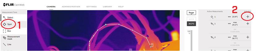
1. Locate the spot function in the left pane and click on it, then place the spot anywhere in the live feed. Once it has been placed, it will pop up in the right pane where the temperature value also is seen.
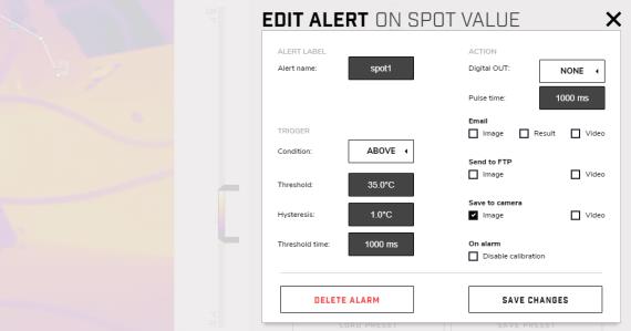
2. Press the Plus sign in the right pane, this will initiate a pop-up screen. From this screen, all the alarm settings are configured. This alarm can be connected to Modbus TCP, MQTT, RESTful API or ONVIF events. Some of these are automatically connected, for example the Modbus TCP alarms are automatically forwarded to the Modbus TCP client, while the Digital I/O needs to be turned on to work.
3. Give the alarm fitting conditions and check the “Save to camera” Image checkbox. Then press Save changes.
4. Now the camera has been configured with one measurement function and one alarm connected to that function. If the camera is connected to another application, for example a VMS or HMI/SCADA system, the web interface could be closed now, and the camera would be able to run on its own.
5. The image below gives a brief description of the main parts of the camera tab. Explore them on your own and connect alarms to some other measurement functions.

Administration tab
The administration tab is used for setting up the camera to talk to other systems and computers. It is divided into five parts; Firewall, SSL certificates, Services, Web protocols and User management. The firewall enables the user to define exactly which protocols that should be allowed through the firewall. For example, if a system integrator creates a system which communicates with the camera over Modbus TCP, then Modbus needs to be allowed through the camera firewall. To enable Modbus, follow the steps below.
1. Navigate to the Administration tab and press Firewall.
2. Check the Modbus checkbox and then press Apply.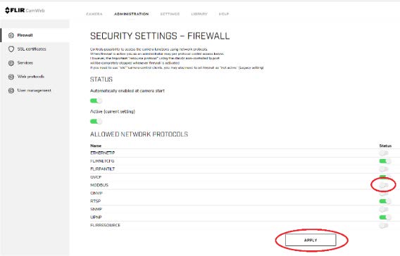
3. Now the camera can communicate with a Modbus client.
The SSL certificates menu enables the user to give the setup a higher level of security by providing SSL certificates.
The Services menu (not to be confused with Service) gives the user control over the FLIR services, which basically is programs being run on the camera itself. For ONVIF to work, the ONVIF process must be run in the camera. To enable ONVIF, press the ONVIF checkbox and then press Apply. Then press Initialize.
Under the Web protocols menu, it is possible to define which web protocols the camera should use. It is not possible to turn both HTTP and HTTPS off as the camera web interface then would be unavailable.
The User management menu contains all the information about the users for the camera web interface. The different user levels have access to different parts of the camera web interface. The viewer for example, cannot configure the camera in any way, only view the video stream and read temperature measurements.
Settings tab
The settings tab contains settings associated with the camera itself, such as the time zone, camera name and network settings. The different menus are quite self-explanatory. To change the camera time zone, go to the Regional settings. To change the camera IP address, go to the Network settings etc. If the camera needs a firmware update, you go to the Systems and Firmware settings menu, here you can also find all the current firmware in the camera which could be useful when discussing known bugs with FLIR support.
Library tab
The library tab is where one will find all the images and videos that is stored when the alarm is triggered, and the camera has been configured to save images or videos locally.
Help tab
The help tab is the camera manual, containing a lot of useful information.
Related Articles
-
 Application Note
Set Up a Local Mail Server and Receive Email When an Alarm is Triggered
Read the Story -
Application Note
Modifying the graphical user interface on the TV CM
Read the Story -
Application Note
Restful API Exercise
Read the Story