Transitioning from the Flea2 to the Flea3 FireWire Camera
Download PDF - Transition_Flea2 _to_Flea3
General Considerations
Other Reference Documentation
Other useful sources of information regarding specific features of the Applicable Product(s) include:
- Flea2 Getting Started Manual
- Flea3 Getting Started Manual
- Flea2 and Flea3 Technical Reference Manuals
Testing Tools
To configure and test the information presented in this TAN:
- Connect the camera’s GPIO pins to an oscilloscope or external trigger source. By connecting the appropriate GPIO pins to an external trigger source or oscilloscope, you can observe the differences in general purpose input/output capability of the Applicable Product(s). Consult your camera’s Technical Reference or Getting Started manual for:
- GPIO connector pin layouts; and
- GPIO electrical characteristics
- Download the FlyCapture SDK. The SDK includes numerous example programs that demonstrate various camera features. Specific examples that relate to this TAN include CustomImageEx, AsyncTriggerEx and SaveImageToFlashEx.
- Access the camera’s register space. The easiest way to try this is using the FlyCap demo software included with the FlyCapture SDK. For register definitions and individual bit descriptions, please refer to the Point Grey Digital Camera Register Reference or your camera’s Technical Reference manual.
Mechanics
The Flea2 and Flea3 share the same form factor and general mechanical properties.
|
Description |
Flea2 |
Flea3 |
|
IR cut filter properties |
The infrared cut-off filter used with color versions of the cameras is the same and has the same transmittance properties. |
|
|
GPIO connector |
Hirose HR25 8 pin connector |
|
|
CCD sensor placement on PCB |
The chip and lens holder mounting holes are centered relative to the four corner mounting holes. |
|
|
Overall dimensions |
Industry standard 29mm x 29mm x 30mm (excluding lens holder and 1394/GPIO connector) |
|
|
Lens holder |
C-mount |
|
|
Case description |
Black zinc (casted) with black aluminum top and Point Grey logo |
|
|
Mass |
58g (excluding including optics) |
|
|
Tripod mounting bracket |
Secured by four (4) M2x2mm screws |
|
|
Mounting holes |
Three (3) M3x2.5mm holes on the bottom face |
|
|
Removable glass / IR filter system |
BW models: protective dust glass between sensor and optics |
|
GPIO Properties
|
Pin |
Flea2 |
Flea3 |
|
GPIO0 (Pin 1) |
Bi-directional input/output |
Opto-isolated input |
|
GPIO1 (Pin 2) |
Bi-directional input/output |
Opto-isolated open collector output |
|
GPIO2 (Pin 3) |
Bi-directional input/output |
Bi-directional input/output |
|
GPIO3 (Pin 4) |
Bi-directional input/output |
Bi-directional input/output |
|
GND (Pin 5) |
Ground pin for all pins |
Ground pin for bi-directional IO, Vext, +3.3 V |
|
GND (Pin 6) |
Ground pin for all pins |
Ground pin for opto-isolated IO pins |
|
VEXT (Pin 7) |
Power camera externally |
Same functionality as Flea2, except on |
|
+3.3V (Pin 8) |
Power external circuitry up to a total of 150 mA. |
Other Hardware and Electronics
|
Description |
Flea2 |
Flea3 |
|
CCD imaging sensors |
648x488 Sony ICX424 |
648x488 Sony ICX618 |
|
IEEE-1394 interface |
9-pin IEEE-1394b (800Mb/s) |
|
|
Power consumption |
Less than 2.5 W |
|
|
A/D converter |
Analog Devices, 12-bit resolution |
|
|
Temperature Sensor |
None |
On-board; accessible via control and status registers (CSRs) |
|
Voltage Sensor |
None |
|
|
Current Sensor |
None |
|
|
LED Behavior |
Same |
|
Firmware
This section does not address the significant number of firmware enhancements that have been added in the Flea3, but focuses on functional differences between the two cameras that could affect integration of the Flea3 in existing Flea2-based applications. Users are encouraged to download the documents listed in Section 1.4.1: Other Reference Documentation for assistance with terms, camera specifications, and register definitions.
|
|
Many default startup (power-up) parameters, such as resolution, frame rate, gain, and shutter, have changed in the Flea3. The memory channels on the Flea3 can be used for creating new default settings. |

|
|
Point Grey cannot predict if or how all of the following differences may affect user applications. This section provides recommendations on how to address some of the most obvious differences in functionality. |
Format_7
|
Description |
Flea2 |
Flea3 |
|
Pixel Formats |
Mono8, Mono16, Raw8, Raw16, YUV411, YUV422, YUV444, RGB8 |
Mono8, Mono12, Mono16, Raw8, Raw12, Raw16, YUV411, YUV422, YUV444, RGB8 |
|
Modes |
||
|
Mode_0 |
Region of interest only |
Region of interest only; yields fastest frame rates |
|
Mode_1 |
2X vertical binning and 2X horizontal subsampling; values are aggregated and averaged; limited or no increase in intensity |
2X vertical and 2X horizontal subsampling; values are aggregated without averaging; increased intensity |
|
Mode_2 |
2X vertical binning; values are aggregated and averaged, with limited or no increase in intensity |
Not available |
|
Mode_3 |
Region of interest only |
Not available |
|
Mode_4 |
Not available |
2X vertical binning and 2X horizontal subsampling; increased frame rate; available on color models only |
|
Mode_5 |
Not available |
4X vertical and 4X horizontal subsampling; values are aggregated without averaging; increased intensity; available on select models |
|
Mode_7 |
Not available |
Region of interest only; improved imaging performance |
Control and Status Registers (CSRs)
|
Description |
Flea2 |
Flea3 |
|
Redefined Registers |
||
|
LUT |
1A40h – 1A44h |
80000h – 80048h |
|
XMIT_FAILURE 12FCh |
No presence bit |
Presence bit |
|
FRAME_INFO 12F8h |
No inquiry bits for each embedded information type |
Inquiry bits for each information type |
|
New Registers |
||
|
Y16 Endianness |
Controlled using IMAGE_DATA_FORMAT 1048h |
DATA_DEPTH 630h |
|
Mirror Image |
MIRROR_IMAGE_CTRL 1054h |
|
|
Y8 or Y16 Grayscale or Raw Bayer Output |
BAYER_MONO_CTRL 1050h |
|
|
Current Sensor Access |
None |
CURRENT 1A58h – 1A5Ch |
Other Firmware Changes
|
Description |
Flea2 |
Flea3 |
|
IIDC Version |
1.31 |
1.32 |
|
Color processing |
Color models output greyscale information when run in standard (Format_0 or Format_1) Y8/Y16 modes. The conversion from raw Bayer information to greyscale is done on-board the camera. |
|
|
Lookup table |
11-bit to 9-bit mapping |
9-bit to 9-bit mapping |
|
Trigger Modes |
IIDC modes 0, 1, 3, 14, 15: Supported on all models |
IIDC modes 0, 1, 3, 4, 5, 14, 15: Supported on all models |
|
Memory Channels |
Two (2) channels for user-defined configuration sets; one (1) channel for restoring to factory default settings |
|
|
Frame Buffer |
None |
32 MB for temporary image storage and re-transmission |
|
Non-Volatile Flash Memory |
None |
1 MB for data storage |
|
Pixel Clocks |
Two (2) or more settings; may change with format/mode change |
Max two (2) settings; will not change with format/mode change |
Software Support
|
Description |
Flea2 |
Flea3 |
|
FlyCapture 2.x Applications |
Supported |
Supported |
|
FlyCapture 1.x Applications |
Supported |
FlyCap Demo GUI does not support new IIDC 1.32 video formats and other new features. |
Related Articles
-
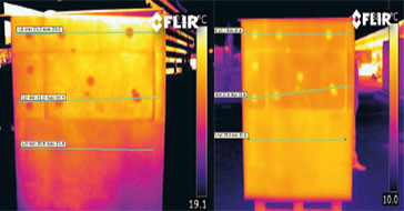 Application Story
FLIR cameras support analysis and diagnosis of external thermal insulation systems
Read the Story -
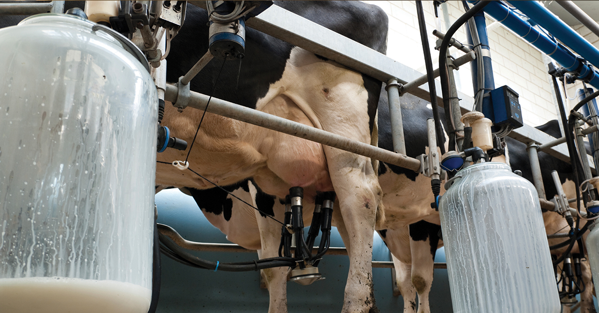 Case Study
Automatic Health Check in Dairy Farms Using FLIR Thermal Imaging Cameras
Read the Story -
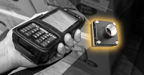 Deep Learning
Comparing Deep Learning Cameras with Smart Cameras
Read the Story