Using Color Correction
Application Note Description
This document provides a description of the color correction matrix (CCM) and provides instructions for the user to calculate a custom CCM.
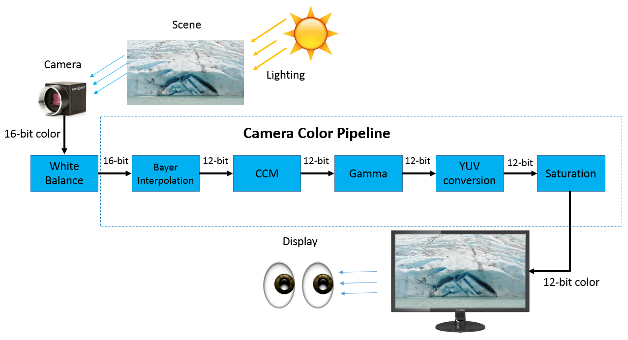
What is Color Correction?
Every sensor has a particular response to lighting and each lighting condition (e.g., sunlight, fluorescent light) has its own emission spectrum which affects how the image appears when captured.
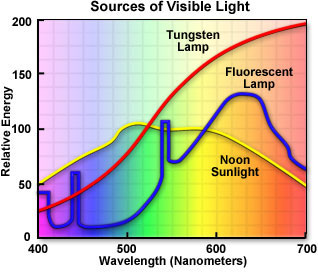
Emission spectrum of various light sources
The sensor’s efficiency at converting photons into electrons is measured as QE and varies depending on the wavelength.
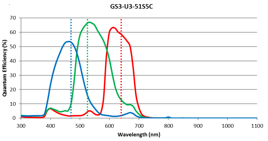
QE of GS3-U3-51S5C (IMX250 sensor)
Color correction takes into account how each color channel interacts with the others, and scales each color channel dependently. A CCM is used to measure and compensate for these interactions.
Why is Color Correction Important?
Reproducing accurate color is important in applications such as inspecting or sorting products, where minor differences in color can affect the accuracy and reliability of results. Blackfly S uses CCM transformations that correct the output image to sRGB color space. This is the most commonly used color space because it provides the “best guess” for how a monitor reproduces color. For more information on the different types of sRGB profiles and their uses, see: http://color.org/srgbprofiles.xalter.
How is Color Correction Implemented?
Color correction is the process of converting the colors displayed in the source image (captured image) to a corrected color target image (final view).
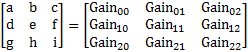
The following example show the calculations for a single pixel:
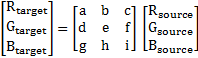
The expanded equation shows the results for each target:
![]()
![]()
![]()
For an image size of n x m pixels, this calculation is performed n x m times.
What is the Difference between CCM and White Balance?
CCM takes into account how the color channels interact with each other and scales the separate channels accordingly. A CCM is non-diagonal and the target RGB values are a function of the RGB values as described above.
White Balance (WB) adjusts for the emission spectrum by scaling each R, G, or B channel independently. A white balance matrix is a diagonal matrix and the target RGB values are scaled by a constant from their source RGB values.
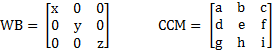
The white balance adjusts colors according to the following equations:
![]()
![]()
![]()
The following images were taken in warm fluorescent light conditions. Compare the results with no color correction methods, white balance only, and white balance and CCM enabled.

From left to right: White balance off, CCM off --> White balance on, CCM off --> White balance on, CCM on
In this example of fluorescent lighting, enabling CCM provides the following transformation to the source image:
![]()
![]()
![]()
How Do I Correct the Color of Images?
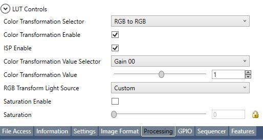
The camera uses predefined CCMs to create the correct sRGB output for different lighting conditions. The predefined CCMs are integrated into the RGB Transform Light source because the CCM cannot be independent of the White Balance (Transform Light Source). The CCM may be set using the SpinView GUI or the API.
The Color Transformation Selector shows the standard option of RGB toRGB. If a different pixel format is used, such as YUV or YCbCr pixel format, the Color Transformation Selector offers the option of RGB to YUV. The CCM changes to account for how YUV encodes color information
To set the CCM in SpinView:
- Connect the camera to the PC.
- Open SpinView.
- Click on the Processing tab and check ISP Enable.
- Check Color Transformation Enable.
- In RGB Transform Light Source, select the appropriate RGB Transform Light Source (warm fluorescent, cool fluorescent, sunny, cloudy, tungsten, shade, general).
To enable CCM in SpinAPI, use the following commands (C++ example):
| CBooleanPtr ptrIspEnable = nodeMap.GetNode("IspEnable"); ptrIspEnable->SetValue(1); CBooleanPtr ptrColorTransformEnable = nodeMap.GetNode("ColorTransformationEnable"); ptrColorTransformEnable->SetValue(1); CEnumerationPtr ptrRgbTransformLightSource = nodeMap.GetNode ( "RgbTransformLightSource"); CEnumEntryPtr ptrRgbTransformationLightSourceWarm = ptrRgbTransformLightSource-> GetEntryByName("WarmFluorescent3000K"); ptrRgbTransformLightSource->SetIntValue(ptrRgbTransformationLightSourceWarm->GetValue()); |
How to Derive Your Own CCM
There are several types of standard target image colors. Below are the typical color targets used:
- sRGB: standard RGB color space. This is the most common color space used for monitors, printers, and the Internet.
- Adobe RGB: provides a larger color space than sRGB.
- CIE XYZ: the color space that maps how a human eye responds to specific wavelengths of light. sRGB and Adobe RGB are subsets of this space.
In some situations, the default settings may not be sufficient for your application. For example, if the target color is not sRGB, it is necessary to use a custom CCM. The example below shows how to convert from the image colors of one (source ) to the image colors of camera (target camera).
To derive a custom CCM:
- Use the following target and source notation to define the target and source cameras.

- Take an image of a standardized color calibration chart under standard lighting conditions. (This example shows a Macbeth color checker with 24 squares.)
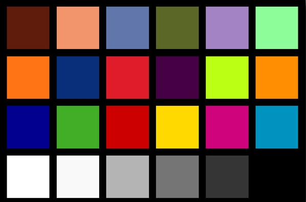
- Determine the average pixel color value in each square to establish 24 unique colors to compare. In these calculations, k = 24 as the 24 average pixel colors in each square:
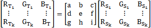
Perform these calculations for both the Target camera [T] and Source camera [S].
- Determine the CCM using matrix multiplication:
![]()
![]()
- With the CCM defined, map the CCM values to the corresponding parameters in the Blackfly S camera. The example below shows mapping the CCM entry to a specific node in the camera.
- Use SpinView to set the gain values for your custom CCM:
a. From the RGB Transform Light Source drop-down list, select Custom.
b. From the Color Transformation Value Selector drop-down, select the specific Gain (e.g., Gain 00, Gain01, etc.).
c. In the Color Transformation Value, enter the calculated CCM index value.
Repeat steps b-c to set all Gain Values for the CCM.
Example code to set the custom CCM in SpinAPI (C++ example)
| CBooleanPtr ptrIspEnable = nodeMap.GetNode("IspEnable"); ptrIspEnable->SetValue(1); CBooleanPtr ptrColorTransformationEnable = nodeMap.GetNode("ColorTransformationEnable"); ptrColorTransformationEnable->SetValue(1); CEnumerationPtr ptrRgbTransformLightSource = nodeMap.GetNode("RgbTransformLightSource"); CEnumEntryPtr ptrRgbTransformationLightSourceCustom = ptrRgbTransformLightSource ->GetEntryByName("Custom"); ptrRgbTransformLightSource->SetIntValue(ptrRgbTransformationLightSourceCustom ->GetValue()); CEnumerationPtr ptrColorTransformationValueSelector = nodeMap.GetNode("ColorTransformationValueSelector"); CEnumEntryPtr ptrGain00 = ptrColorTransformationValueSelector->GetEntryByName("Gain00"); ptrColorTransformationValueSelector->SetIntValue(ptrGain00->GetValue()); CFloatPtr Gain00Value = nodeMap.GetNode("ColorTransformationValue"); Gain00Value->SetValue([Enter CCM Value]); |